The first example was already discussed in the previous section, it creates the conjugate boundary contour and an initial triangulation for a family of triply periodic minimal surfaces including the CLP surface.
Like for all other subprojects of Time-Object the description file
CLP.bd is read in with the ![]() button, for
Surface_Build instances the surfaces then are computed
automatically. The CLP.bd description file should be located in the
geometry/build_diri subdirectory of the GRAPE demo
directory:
button, for
Surface_Build instances the surfaces then are computed
automatically. The CLP.bd description file should be located in the
geometry/build_diri subdirectory of the GRAPE demo
directory:
#
# CLP.bd: test object for surface_build - one-parameter family of CLP surfaces
#

# task
GEOMETRY;


# frame data
0; 5;           # frame / number of frames


# no parameter
0; 0;


# number of parts / number of points
2; 6;


# ruler flags / point coordinates
0; 0; 0;       0.0;     0.0;     0.0;
1; 0; 0;   0.5 + t;     0.0;     0.0;
1; 2; 0;   0.5 + t; 0.5 + t;     0.0;
0; 2; 0;       0.0; 0.5 + t;     0.0;
0; 0; 3;       0.0;     0.0; 1.5 - t;
1; 0; 3;   0.5 + t;     0.0; 1.5 - t;


# flag / type / patch type / point indices / u- and v-lines, sub-points
0; 0; 4;   0; 1; 2; 3;   7; 7; 0; 0;
0; 0; 4;   1; 0; 4; 5;   7; 7; 0; 0;
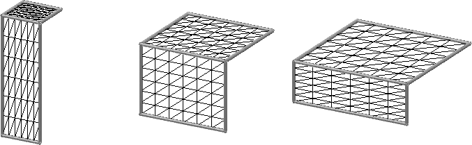
Figure 8.18: Conjugate boundary contour for a family of triply periodic minimal
surfaces with a basic triangulation. The picture shows three out of the
five frames created by reading the CLP.bd description file
including the conjugate contour of the CLP surface in the middle.
The second example is just a quadrilateral patch with two straight lines, one circle arc and a spline as boundaries, the corresponding file is dummy.bd. In this example not the points but the spline tangents can be edited interactively since they are bound to rulers:
#
# test quadrilateral with circle and spline boundaries
#

# task
GEOMETRY;


# frame data
0; 1;           # frame / number of frames


# no parameter
0; 0;


# number of patches / number of vertices
1; 8;


# ruler flags / point coordinates
0; 0; 0;   0.0; 0.0; 0.0;
0; 0; 0;   1.0; 0.0; 0.0;
0; 0; 0;   1.0; 1.0; 0.0;
0; 0; 0;   0.0; 1.0; 0.0;
0; 0; 0;   0.5; 1.0; 0.0;    # circle midpoint
0; 0; 0;   0.0;-1.0; 0.0;    # circle normal
1; 2; 1;   0.2; 1.0; 0.2;    # spline tangent at start point
3; 0; 4;   1.0; 0.0;-3.0;    # spline tangent at end point


# flag / type / patch type /point indices /u- and v-lines, sub-points
0; 1; 4;  0; 1; 2; 3;   7; 4; 0; 0;
   02010; 0; 6; 7;           # spline with fixed points
   00220; 0;                 # straight line
   00404; 0; 4; 5;           # circle with circle restriction
   00220; 0;                 # straight line
Because the spline is not planar the only option is to fix its points, for the straight lines the points are allowed to move along them. For the circle we could use the restrictions 00004 (restrict the points to the circle), 00040 (restrict the points to the plane of the circle) and of course 00010 (fully fixed). Add the Diri project (which includes Build), read in the file and try out "mollify-send" with the boundary option enabled (see 7.4.3.7) or the refine methods (see 8.2.8) to see how the circle restriction works.
Copyright © by the Sonderforschungsbereich 256 at the Institut für Angewandte Mathematik, Universität Bonn.