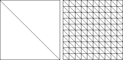
Figure 8.8: The starting triangulation and the refined one
After starting the interactive package and adding the project grid-edit we switch to the first options menu opt1 and start with a macro triangulation of the square domain, consisting of two triangles (cf. Fig. 8.8). This can be generated using add triangle with a background grid or one of the GRAPE methods explicit or mask-make sent to class ADAPT2D. After refining this grid (cf. Fig. 8.8) with quarter all triangles (one of the three possibilities to refine a grid) we want to clip out the first ellipse.

Figure 8.8: The starting triangulation and the refined one
To do so we change the current display-method by pressing the button disp. Then the caption of this button changes to disp -> and we can choose ellipse, the display-method we have to take into account here. In opt0, where all the rulers of display-methods are added, there are five new rulers to adjust the position, length and height of the ellipse. To fix the changes of our mesh we have to press fix clip. The ellipse is stored as a boundary function only when clip-fix is used on an object of class ADAPT2D. Then we can change the display-method back to the standard display by pressing the disp button twice. The result is shown on the left hand side of Figure 8.9.
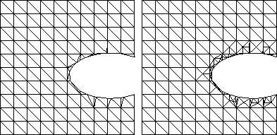
Figure 8.9: After clipping out an ellipse and boundary refinement
Now we refine the boundary along the ellipse to get a smoother curve. At first we the button init refine field to initialize the information in the ADAPT2D structure which is misleading after clipping, removing, adding, modifying and swapping. Then we can use ref border and mark the first and last segment (counterclockwise with the left mouse button) of the boundary we want to refine. After the refinement is performed (cf. Fig. 8.9) the new nodes on the mesh boundary were automatically pushed onto the boundary curve of the ellipse. Next we optimize the mesh by calling the methods mollify or optimize several times (cf. Fig. 8.10).
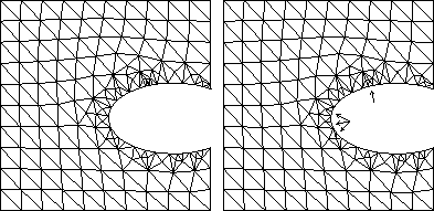
Figure 8.10: With mesh optimization and some handwork
In the areas where we are not content with the triangulation we refine or coarse some triangles by hand using refine pick or coarsen pick (cf. Fig. 8.10). Now we apply the same procedure to a second ellipse (cf. Fig. 8.11), adjusting the parameters and fixing the geometry as described above.
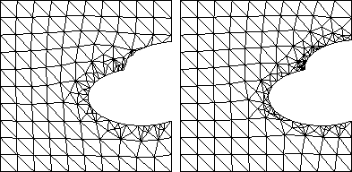
Figure 8.11: The same procedure with a second ellipse
Next we try to make the actual triangulation (cf. Fig. 8.12, left) more regular and uniform along the boundary. To do this we at first use Delaunay swap and then remove the points which are not needed by picking them after pressing del point. The result shown on in the right hand side of Figure 8.12 seems to be very convincing concerning the smoothness along the border and the angles in the triangles and forms a good starting mesh for a numerical algorithm.
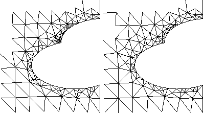
Figure 8.12: A zoom to show the `quality' of the grid along
the boundary before and after using del point and Delaunay swap
Copyright © by the Sonderforschungsbereich 256 at the Institut für Angewandte Mathematik, Universität Bonn.